CCNA Study Guide Logo

Monday, August 23, 2010

1.4 Common TCP and UDP Network Applications

Before you continue reding this topic, please make sure you already understand our previous topic about OSI and TCP/IP Model.

In TCP/IP, a port is mecanism that allow a computer to have more than one session to communicate with other computer or other devices in internetwork. A port can identify a specific process to which a computer or other network message need to be forwarded when it arrives at a destination device.

A port number is 16 bit that will append to header of message unit. 16 bit mean 2^16 equal to 65536 ports (0 to 65535). Based on the protocol, port can be categorize to Transmission Control Protocol (TCP) and User Datagram Protocol (UDP).

So, what is TCP and UPD ?
  • Transmission Control Protocol (TCP)
    TCP is the transport level protocol that provides reliability and ordered delivery of stream. Major internet application rely on TCP, such as WWW, e-mail, FTP, etc.
  • User Datagram Protocol (UDP)
    UDP is a simple transmission model with no hand-shaking process for guaranteeing reliability, ordering, or data integrity. UDP provides an unreliable transmission, a datagrams may arrive out of order, duplicated, or can go missing without any notice to sender nor receiver. No error checking and error correction performed to avoiding overhead processing at network. UDP mostly used by time sensitive application that prefer dropping packet than waiting for delay (opposed to TCP transmission). Because of this nature, UDP is very usefull for servers that answer small queries from huge number of clients. Common application : Domain Name System (DNS), Voice over IP (VoIP), Trivial File Transfer Protocol (TFTP), etc.

Based on the numbering, TCP and UDP divided into 3 categories :
  • Well-known Port
    According to Internet Assigned Number Authority (IANA), well-known port numbers are port 0 to 1023. This list specifies the port used by the server or application process as its contact port.
  • Registered Port
    Range 1024 to 49151. These ports used by computer vendors for their applications and operating systems. Registered port also register to IANA.
  • Dynamically Assigned Port
    Range 49152 to 65535. These ports assigned by applications or operating system to serve request from clients/users.

There are many TCP and UDP ports number that can be found in IANA site. But lets make it easy, with some list of common TCP and UDP ports that you can find at table 1 below.

Table 1. Common TCP and UDP Ports
TCP
UDP
Port
Application
Port
Application
20
FTP Data
53
DNS
21
FTP Control
69
TFTP
22
SSH
161
SNMP
23
Telnet
25
SMTP
80
HTTP
110
POP3
443
HTTPS

You can find more common TCP and UDP ports by identifying your day to day basis application port number, such as Network Time Protocol (NTP), Remote Desktop, etc.
Wednesday, August 18, 2010

1.3 Sample CCNA exam (OSI and TCP/IP Model)

This sample CCNA exam will review your knowledge about OSI and TCP/IP Model.

Questions :
  1. You issue ping command and you get output shows “request times out”. Which OSI layer this problem reside ?
  2. Which layer of the OSI model is responsible for ensuring reliable end-to-end delivery of data?
  3. At which OSI layer is a logical path created between two host ?
  4. The acknowledgement of transmissions, sequencing, and flow control across a network. At which OSI layer ?


Answers :
  1. Network layer
    ICMP is a protocol designed to help manage and control the operation of a TCP/IP network. The ICMP protocol provides a wide variety of information about a network's health and operational status. Ping belong to this ICMP, and ICMP belong to Network layer in OSI layer.
  2. Transport layer
  3. Network layer
  4. Transport layer

Tuesday, August 17, 2010

1.3 OSI and TCP/IP Model

The Open Systems Interconnection model (OSI model) defined by Open Systems Interconnection, while the Transmission Control Protocol/Internet Protocol (TCP/IP) model was created by Departement of Defense (DoD).

Lets take a look at OSI 7 layer model and comparison to TCP/IP model.

Table 1 – OSI Model Summary
Layer
Function Description
Sample Protocols/Technologies
7. Application Interfacing between communications software and any applications that need to communicate outside the computer. It also define proccess for user authentication.
HTTP, Telnet, DNS,DHCP, SNMP, FTP, TFTP, SMTP, POP3, NTP
6. Presentation Data representation (define and negotiate data formats),encryption and decryption.
SSL, Shells and Redirectors, MIME
5. Session Interhost communication. How to start, control, and end conversations (called session). An application can be notified if some of series of messages are completed. Allow presentation layer to have view of an incoming stream of data.
NetBIOS, Sockets, RPC
4. Transport End-to-end connections and reliability,error recovery, and Flow control
TCP and UDP, SPX, NetBEUI/NBF
3. Network Three main feature : logical addressing, routing (forwarding), and path determination. IP Address, routing protocols, and routing table belong to this layer
IPv4, IPv6, IP NAT, IPsec, ICMP, IPX, Routing protocols
2. Data Link Defines how data is formatted for transmission and how access to the network is controlled. This layer has been divided by the IEEE 802 standards committee into two sublayers: media access control (MAC) and logical link control (LLC).
IEEE 802.2 LLC, Ethernet Family; Token Ring; FDDI, IEEE 802.11 (WLAN, Wi-Fi),ATM, SLIP and PPP
1. Physical Media, signal and binary transmission. Refer to standard of physical characterstics of transmission medium such as connector, pins, use of pins, electrical currents, encoding, light modulation, and other rules about physical medium
Physical layers technologies (RS-232, Full duplex, RJ45, V.35,T1, E1, 10BASE-T, 100BASE-TX, POTS, SONET, SDH, DSL, 802.11a/b/g/n, etc

Table 2 will show you comparison of OSI model and TCP/IP model, also encapsulation at each layers.

Table 2 - OSI vs TCP/IP Model, and encapsulation at each layers
OSI Layer
TCP/IP Layer
Encapsulation Units
Encapsulation Proccess
7. Application 4. Application Data Data
6. Presentation Data Data
5. Session Data Data
4. Transport 3. Transport Segments TCP/UDP HeaderData
3. Network 2. Internet Packets IP HeaderTCP/UDP HeaderData
2. Data Link 1. Network Access Frames MAC HeaderIP HeaderTCP/UDP HeaderDataCRC
1. Physical Bits Transmit into Physical Media (Bit Format)

Talking about encapsulation, bits transmitted from sender over physical media, at the receiving device will de-encapsulated from bits into frames, and so on untill arrived at Application layer.

Please find Sample CCNA exam (OSI and TCP/IP Model) to check if you already understand this material.

Thursday, August 12, 2010

1.2 Devices required to meet a network specification

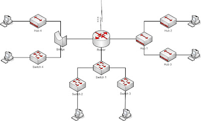
As mentioned in section 1.1, we already knows something about router, switch, and hub, also bridge as addition in internetwork. Figure below shows how network look with all of those internetwork devices in place. Please note that left and right part of this figure are not commonly use this day (we can say that bridge and hub are old technology). Typical network this day can be found in middle part (switch 1, 2, and 3).

Devices required to meet a network specification
Figure 1

Remember that a router will not only break up broadcast domain in every LAN interfaces, but also it will break up collision domain as well.

Notice that we use bridge, it break up collision domain, operate similary with switch. Hub does not break up collision domain, we can say that every devices connected to hub belong to the same collision domain.

The best network connected to the router is the LAN switch network in the middle. Why ? Because each port on switch has its own collision domain. Well, we still can enhance this LAN switch in the middle. Since its still belong to the same broadcast domain, it can turn into bad thing. Imagine if the broadcast domain too large, so all devices must listen to all broadcast transmitted, the users then have less bandwidth and require to proccess more broadcast, as result network response time will slow. We can do enhancement by using separate VLAN (Vitual LAN) for each switches to meet bussiness requirement. For example Switch 2 using VLAN 100 to serve users in IT Departement, Switch 3 using VLAN 200 to server Accounting Departement. This will separate or break up broadcast domain, router still need for interVLAN communication.

Ok, let’s back to Figure 1 above ..
How many broadcast and collision domains are in this internetwork ?
Leave your answer in comment box below .. C U..

Wednesday, August 11, 2010

Simple Cisco Switch Traffic Shaping

Why would we need to limit bandwidth on cisco switch ?
I never think why until my friend ask me how to do that couple of times (may 2 months ago). Here is a sample scenario and configuration on cisco switch to limit interface bandwidth.

Sample Scenario
As you can see on figure 1, we need to connect Customer LAN in building A to LAN building B. We need to limit their bandwidth to for example 256Kb because customer pay less $ in amonth. Ok, lets jump to configuration detail. We will skip in depth discussion of QoS and how it works (check Cisco QoS for detail).

We need globally enable QoS with the “mls qos” configuration command. This command will enable QoS on all ports with default settings. “mls qos” is the key, without it, our next steps will be use less.

SW(config)#mls qos

Define criteria to select traffic for policing, define a class-map to select traffic using defined criteria, define a service-policy using class, and applying a policer to the specified class.

SW(config)#class-map all_traffic
SW(config-cmap)#match ip dscp 0
SW(config-cmap)#exit
SW(config)#policy-map limit_256
SW(config-pmap)#class all_traffic
SW(config-pmap-c)#police 256000 32000 exceed-action drop
SW(config-pmap-c)#


Apply a service policy to a port

SW(config)#int fa0/13
SW(config-if)#service-policy output limit_256
SW(config-if)#service-policy input limit_256

OK, we are done !
We need to check whether what we have done already work properly or not.

SW#sh policy-map int fa0/13 | i rate
30 second offered rate 0 bps, drop rate 0 bps
30 second rate 0 bpsqm_police_inform_feature: CLASS_SHOW
30 second offered rate 0 bps, drop rate 0 bps
30 second rate 0 bpsqm_police_inform_feature: CLASS_SHOW
SW#

It’s normal that we don’t see any traffic count with above command on switch, but if we issue above command on router and no traffic counted, then be aware, maybe you missed something. Otherwise, the following command will show you some counter (if configuration work).

SW#sh mls qos int fa0/13 statistics
FastEthernet0/13
Ingress
dscp: incoming       no_change      classified      policed      dropped (in bytes)
Others: 208054281    192207476    15846805      0           4398
Egress
dscp: incoming       no_change      classified      policed      dropped (in bytes)
Others: 368212302        n/a                n/a                 0                4593

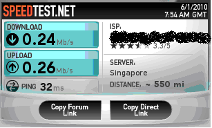
Finally, here is test result to speedtest…

Speed Test Result
 
© Copyright 2010. CCNA Study Guide. All rights reserved | CCNA Study Guide is proudly powered by Blogger.com | Template by o-om.com
Edited by CCNA Study Guide August 2010.